Presentations
MES Detection System
The MES or Molecular Emission Spectrometer is the heart of the TGM.
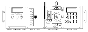
Certain gases emit light when they pass through a hydrogen flame. The MES detection system supports a hydrogen flame in the reaction chamber of the Detection Module. The hydrogen that supports the flame is supplied at a flow rate of 0-300 cc/min by a mass flow controller (MFC). The flow rate is read and set on the digital display of the Hydrogen Flow Control Module, typically at 55% of flow (55% of 300 = 165 cc/min).The air flow rate is controlled by an orifice in the reaction chamber, typically at 0.8 liters/min (lpm) with the flame on. The flow rate of sample air is read by pushing a button on the Air Flow Module.
In the S2/CE configuration, a second flowmeter was added so that both sample and bypass air flows may be read, and a vacuum gauge was added as a troubleshooting aid.
The air and hydrogen combine to support the flame continuously. The MFC and flow control orifice hold the flame within tight limits for stable and repeatable readings. The Detection Module's reaction chamber is heated and temperature controlled at 100°C. This keeps the water formed (from burning hydrogen) in the vapor phase, and it helps to control the flow of air through the orifice. The reaction chamber includes an igniter to light the flame and a flame detector that senses when a flame is present.
 The flame is managed and controlled by the Manager Module. LED's on this module indicate conditions about the Detection Module:
- 70 W Heater: cycles on and off with the reaction chamber heater.
- Flame Enable: shows that switch SW1 is on. If off, the flame can not auto-ignite. It must be on in normal operation.
- Ignition: When the flame detector senses that a flame is present, this light is on. It is on when the flame is lit.
- Auto Re-Ignite: This LED indicates that the Manager Module is in the process of re-igniting the flame. It is off at all other times.
Operating Principle
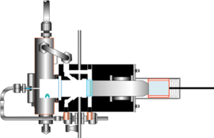
Hydrogen enters the lower left side of the reaction chamber, and the air sample enters at the bottom through a sample nozzle. Air and hydrogen combine to form the flame that is constantly fueled by the hydrogen supply and the oxygen in the air sample. This flame is at the tip of the sample nozzle, in the middle of the reaction chamber. The flame constantly emits light, which is detected by the dual PM tube. The PM (photomultiplier) tube is a photon counter, extremely sensitive in the visible light region of the spectrum.The normal zero reading is a flame-on reading, which is hundreds of units different from the flame-off zero. The flame light passes through a dual optic filter. The optic filter has a measuring and a compensating wavelength region. It is aligned with the dual PM tube, such that the light reaching the left PM tube section is optically filtered at the measuring wavelength (Channel A) while the light reaching the right PM tube section is optically filtered at the compensating wavelength (Channel B). The signal produced and read on the Manager Module display is the Channel A signal minus the Channel B signal.
 Channel A - Channel B is adjusted to read at or near zero. When a toxic gas comes in with the air sample, it increases the light emission in both channels. But, it increases the emission in Channel A to a much greater degree than the emission of Channel B. So, the signal (Channel A - Channel B) increases as a positive number. The greater the concentration of toxic gas, the greater the positive reading.
Some gases, which are not toxic but may be present in the background air, also cause an increase in both the Channel A and Channel B readings. Most often, such gases are solvent vapors from alcohols or other organic chemicals used in semiconductor production facilities. These gases emit more light at the compensating or Channel B wavelength than at the measuring or Channel A wavelength. Since Channel B is subtracted from Channel A, a negative signal is produced. The MES is adjusted by a technician so that the signal is only slightly negative by using the Balance pot while solvent vapors are added to the air sample.
The flame is in the middle of a circular cavity (hole) in the reaction chamber. The flame light passes to the dual PM tube through a sapphire burner window and the dual optic filter. The sapphire window seals off the flame chamber and isolates the hot and wet gas of the flame from the optics, while letting the flame light pass through it. A housing bolts onto the front side of the reaction chamber that holds a second, smaller sapphire LED window and a fiber optic cable. Separated from the hot reaction chamber by the fiber optic cable is a blue light LED. Nearly all toxic metal gases have a peak light emission in the blue light wavelength region, which corresponds to the wavelength passed by the measuring optic filter. This LED emits light at the peak wavelength, and the light passes through a small hole in the middle of the circular cavity.
The blue light LED simulates the light produced when toxic gases come into contact with the flame. The LED is turned on once per day to confirm that the MES is responsive and working, a test that most gas detection methods are unable to perform automatically. The LED test is also used to determine if the MES detection system needs to be serviced or adjusted in any way.
An exhaust manifold bolts onto the reaction chamber. The TGM's vacuum pump connects on the top. The pump draws sample air through the reaction chamber. The flow is set and maintained by the a #36 (0.36 mm) orifice installed in the exhaust manifold.
